
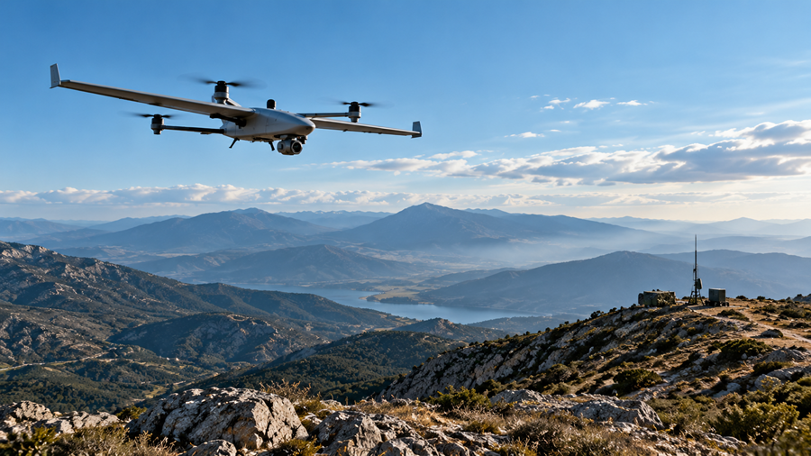
Conceptual UAV-to-ground communication scenario. Terrain, platform movement and radio geometry can affect connectivity independently of navigation performance.
Why a resilient UAV communications architecture requires more than a strong transmitter – and how to evaluate multi-hop connectivity, network traffic and radio integration.
A UAV approaches a ridgeline. Its onboard navigation system may still provide a valid position, velocity and attitude estimate, yet the radio link to the ground control station is beginning to fade. The aircraft may know where it is while the operator can no longer reliably receive telemetry or video. These are two distinct engineering problems: navigation resilience and communications resilience.
Would another UAV, a ground vehicle or a portable radio node help? Potentially. MANET mesh networks for UAVs can route traffic through a compatible intermediate node when a direct radio path becomes unavailable, provided the required RF links remain usable. However, each additional hop introduces trade-offs in network capacity, latency and overall performance.
This distinction matters for unmanned system integrators. As discussed in our earlier Insight on GNSS-denied UAV navigation, keeping the navigation solution trustworthy requires a defined sensor and integrity architecture. Maintaining the communications link requires its own RF and network design. Neither capability automatically solves the other.
How MANET Mesh Networks for UAVs Differ From Direct Radio Links
A conventional point-to-point configuration connects a platform to a designated ground endpoint. When the received signal falls below a usable level – because of terrain obstruction, changing antenna orientation, distance or interference – the link may degrade or fail. Adding transmit power alone cannot always overcome an obstructed path or a poorly located antenna.
In a MANET, compatible radios act as network nodes. Depending on the waveform and configuration, a node can send its own traffic and help forward traffic originating elsewhere. The available topology changes as nodes move, join, leave or experience different RF conditions. This is the practical meaning behind terms such as self-forming and self-healing: the network can discover and use available paths without a fixed, single-hop arrangement.
Self-healing is a routing capability, not a promise of uninterrupted service. A new path must still satisfy radio compatibility, propagation, capacity and configuration requirements. If no usable next hop exists, the network cannot create connectivity from nothing. For an overview of the hardware and application range, see General Guidance Mesh Products.
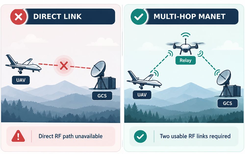
When the Direct Link Fails: A Three-Node Scenario
Consider three nodes: UAV A, relay B and ground station C. UAV A moves behind a hill and its direct A-C connection becomes unreliable. Relay B, positioned where it has suitable RF connectivity to both endpoints, may allow traffic to follow A-B-C instead. The example illustrates a network option, not a specific deployment, field test or guaranteed range.
The first question is physical: can A reach B, and can B reach C at the required data rate? The second question is logical: are all three radios configured for a compatible waveform, frequency plan, security settings and network behavior? The third is operational: will the resulting end-to-end path support the application while the nodes are moving?
If B turns, descends, loses power or becomes blocked by terrain, the alternative route can disappear as quickly as the direct link. If B has to forward several video streams, the radio resources available to other users may also be reduced. A successful three-node demonstration therefore needs more than a connectivity icon on a screen: it needs sustained measurements of useful throughput, delay, loss and recovery behavior.
What Actually Determines MANET Performance?
RF geometry and the link budget
Every hop is still a radio link. Antenna gain, antenna pattern, placement, polarization, cable losses, frequency, receiver sensitivity, transmit power and the surrounding terrain determine whether the signal can be used. On a moving aircraft, bank angle and antenna shadowing can change coverage even when the geographical distance remains similar. A relay may improve geometry, but it does not remove the need for sound antenna engineering.
It is also important to distinguish a manufacturer’s stated maximum distance from an engineering link budget. Range figures are highly dependent on antenna systems, line of sight, radio settings and the environment. That is why the right question is not simply “How far does this radio reach?” but “What availability and data performance can this installation deliver along the intended mission envelope?”
Hop count, throughput and latency
A multi-hop path carries the same information across more than one RF transmission. On a shared wireless channel, forwarding consumes airtime, and transmissions may compete for the same resources. The available application throughput can therefore be substantially lower than a headline PHY or mesh-capacity value, particularly where several users converge on a common relay. Retransmissions, coding choices, congestion and route changes also affect delay and jitter.
DTC specifies high mesh-capacity figures for its MeshUltra family, but these are configuration-dependent capabilities, not guaranteed per-user throughput on every hop. For design purposes, test delivered application data at the receiving endpoint with realistic node counts, hop lengths and simultaneous traffic. A reliable network budget is more useful than a radio data-sheet number by itself.
One network, different traffic requirements
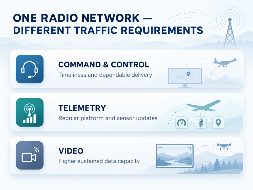
Command-and-control (C2), telemetry and video can share the same MANET infrastructure, but they do not place identical demands on it. C2 traffic is often modest in size yet time-sensitive: commands and safety-relevant acknowledgements must arrive within the application’s allowed time window. Telemetry normally consists of regular, relatively small status updates, but late or missing updates can degrade the operator’s awareness of platform state.
Video tends to require more sustained bandwidth, with performance influenced by codec, resolution, frame rate, buffering and packet loss. A lower-bitrate stream may be preferable to an unstable high-definition stream when capacity is constrained. Traffic prioritization, if available in the selected configuration, should be verified in practice rather than assumed from the term “mesh” alone.
Interference, spectrum and network resilience
Adaptive modulation, coding and dynamic routing can help a compatible system respond to changing link conditions. They do not make the radio immune to interference or deliberate jamming. If the spectrum is unusable at critical nodes, alternative routes may fail too. Frequency authorization, antenna filtering, emission constraints and the operational interference environment belong in the initial requirements, not in late-stage acceptance testing.
Choosing the Right MANET Radio for an Unmanned Platform
The right radio depends on platform constraints and network role. A compact aerial node may have very little allowance for mass, heat or electrical load. A mobile command vehicle can accommodate more RF power, antennas and rugged interfaces. Neither should be evaluated using transmitter watts alone. DTC’s BluSDR family spans these different classes within a broader portfolio of tactical radio communication solutions.
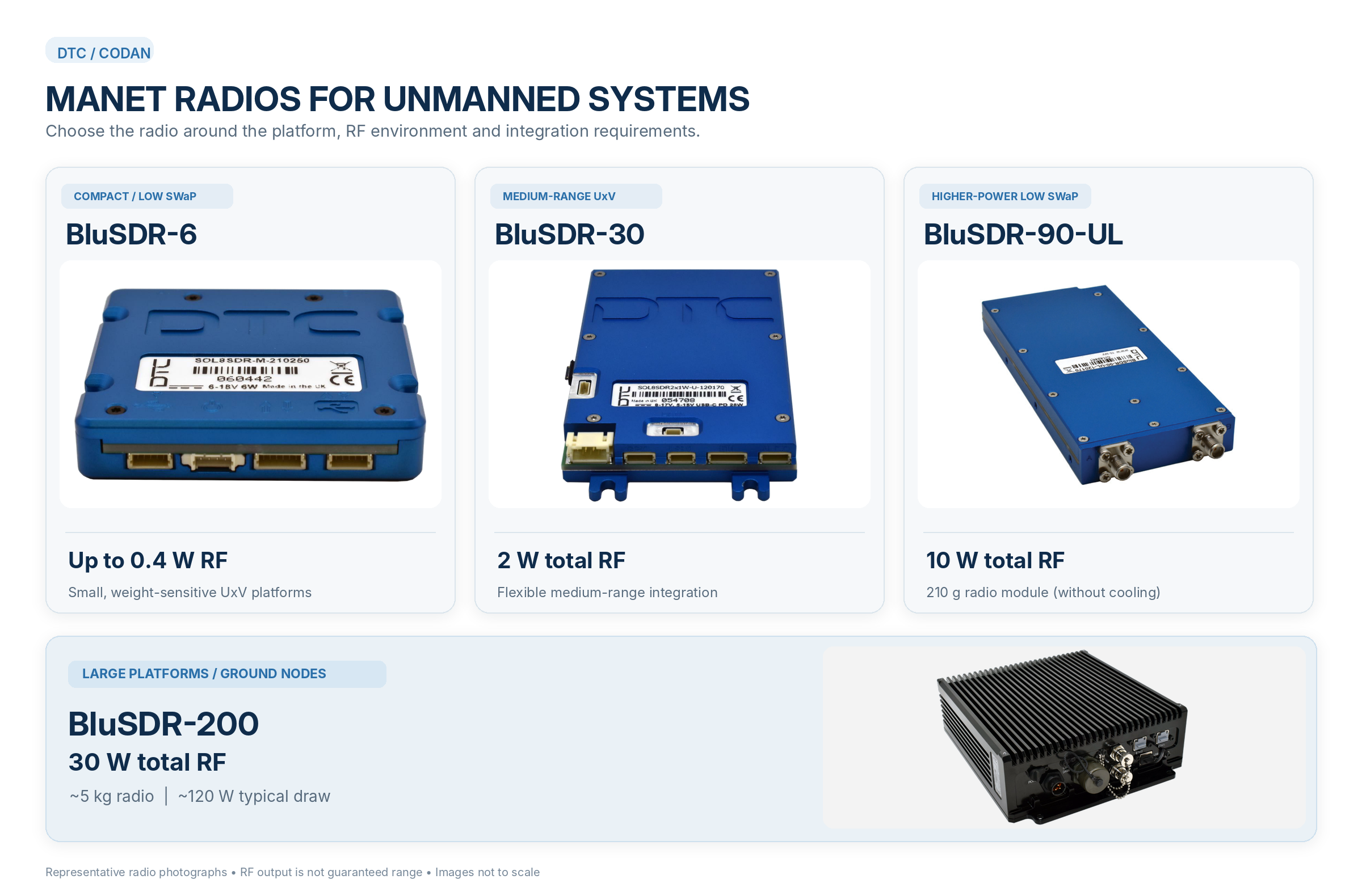
The comparison below uses specified hardware variants. The weight of a core PCB must not be confused with the mass of a fully installed radio, antennas, mounting hardware, wiring and cooling.
| MODEL | RF OUTPUT | REFERENCE MASS | INTEGRATION CONSIDERATION |
|---|---|---|---|
| BluSDR-6 | Up to 0.4 W total (band-dependent) | Approx. 26 g core PCB | Small, SWaP-constrained UAVs; boxed builds and full installation weigh more. |
| BluSDR-30 | 2 W total | Approx. 110 g Clamshell Core | Compact UxV platforms; additional interfaces and enclosure variants alter weight and cooling needs. |
| BluSDR-90-UL | 10 W total | 210 g bare module | Higher RF output for suitable platforms; external thermal management is required. |
| BluSDR-200 | 30 W total | Approx. 5 kg radio | Large airframes, mobile or fixed ground nodes; approx. 120 W typical power demand. |
BluSDR-6: start with the smallest platform constraints
BluSDR-6 is the most compact option in this comparison, with a core PCB mass around 26 g for specified variants and up to 400 mW total RF output, depending on band. That makes size, integration access and power budget central design considerations. The 26 g number refers to the core PCB; the enclosed unit shown in some photographs is heavier. It is not evidence that the complete installed communications system weighs 26 g.
BluSDR-30: a step up in RF output and interfaces
BluSDR-30 provides 2 W total RF output, with Gigabit Ethernet, serial and USB options across applicable variants. DTC currently specifies 110 g for the Clamshell Core build; boxed versions have different masses. This is a useful illustration of why engineers must quote the exact hardware option rather than repeat a legacy family brochure figure. Connector access, USB-C power support, environmental protection and thermal design should be checked against the selected build.
BluSDR-90-UL: more RF output, but not free of thermal cost
At 10 W total RF output and a listed module mass of 210 g, BluSDR-90-UL addresses applications needing higher transmit power without moving immediately to a large rugged radio. However, the module requires external heatsinking or forced cooling as appropriate; the manufacturer also lists a heavier heatsink assembly. Treating the 210 g module figure as the mass of a complete installation would understate system SWaP.
BluSDR-200: relevant to the network, not to every UAV
BluSDR-200 extends the family to 30 W total RF output in a rugged enclosure, with dual HD-SDI video inputs and extensive interfaces. At approximately 5 kg and around 120 W typical consumption, it is a different class of device. It may be appropriate for large airframes and mobile or fixed ground-side roles where those constraints can be accommodated; it is not a sensible default for a small battery-limited multirotor.
A family-level choice is only the first step. Actual interoperability and network behavior depend on matching waveform variants, frequency bands, firmware, licenses and configuration. The DTC BluSDR family overview provides the broader product context, while the final bill of materials should be based on the selected radio variant and manufacturer documentation.
Beyond the Airframe: Ground Nodes and Network Management
A UAV data link is rarely just an airborne radio and one antenna on the ground. The broader communications architecture may include an elevated relay, a mobile ground vehicle, a fixed station and a command post. Each element can contribute reachability and resilience, but it can also become a bottleneck when traffic aggregates or one radio link becomes weak.
The illustration below shows a conceptual network, not a validated physical topology. Lines distinguish kinds of application traffic for readability; blue and teal markings do not imply that C2, telemetry and video require separate RF channels. Depending on design and available capacity, those streams may traverse the same compatible mesh links. An engineering review should identify traffic sources, destinations, permitted routing behavior and what happens when a critical node disappears.
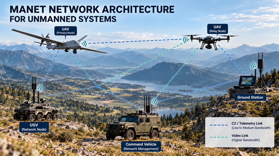
Network visibility matters as much as network formation. DTC Mission Commander provides tools for monitoring and managing supported transmission assets, mapping equipment and handling selected video, spectrum and configuration functions. For an integrator, the objective is to connect network management to operational decisions: identify a deteriorating link, understand whether a viable alternate path exists, and recognize when application service levels are no longer being met.
What Should Engineers Verify Before Selecting a MANET Radio?
Before requesting a quotation, turn the mission scenario into testable requirements. The following checks are more useful than choosing a product by output power or a single maximum range figure.
- Define the platform envelope. Record available electrical power, allowable installed mass, mounting space, cooling, vibration environment, antennas and interface requirements – not just the bare radio mass.
- Specify the application traffic. State minimum and peak video data rate, telemetry update needs, C2 timing limits, acceptable packet loss and the consequences of an interrupted connection.
- Describe the network topology. Identify which nodes may move, which nodes may relay traffic, expected concurrency and which routes remain viable when a radio or link disappears.
- Validate RF and regulatory conditions. Confirm operating bands, spectrum permissions, antenna placement, line-of-sight assumptions, coexistence constraints and environmental interference.
- Verify configuration and protection. Check waveform compatibility, software and licensing, available encryption options, key management and the selected network-management interfaces.
- Test the complete system. Measure end-to-end delivered throughput, latency, jitter, packet loss and recovery under representative motion, loading and link degradation; record when the mission should enter a safe fallback state.
A useful acceptance test includes at least one degraded-link case and one relay-loss case. It should also verify that critical control traffic remains within its application limits while realistic telemetry and video are present. A mesh that looks connected at idle may behave very differently under load.
Building the Right Communications Architecture
When designing MANET mesh networks for UAVs, engineers must evaluate the complete communication architecture, including RF coverage, relay availability, network capacity and integration constraints.
MANET technology can make an unmanned system communications architecture more flexible by allowing compatible nodes to forward traffic over available alternative paths. Its value is not that every link survives, but that the system designer gains more possible ways to maintain a required service when conditions change.
Selecting the right solution therefore starts with platform SWaP, traffic requirements, RF geometry, network roles and a realistic test plan. The DTC BluSDR family offers options from compact UAV modules to higher-power, rugged network nodes; the engineering task is to match the specific hardware and waveform configuration to the actual mission.
General Guidance works with DTC to help integrators assess communication requirements, compare suitable radio options and coordinate technical questions with the manufacturer.
Discuss Your UAV Communication Requirements:
Contact: sales@general-guidance.com