
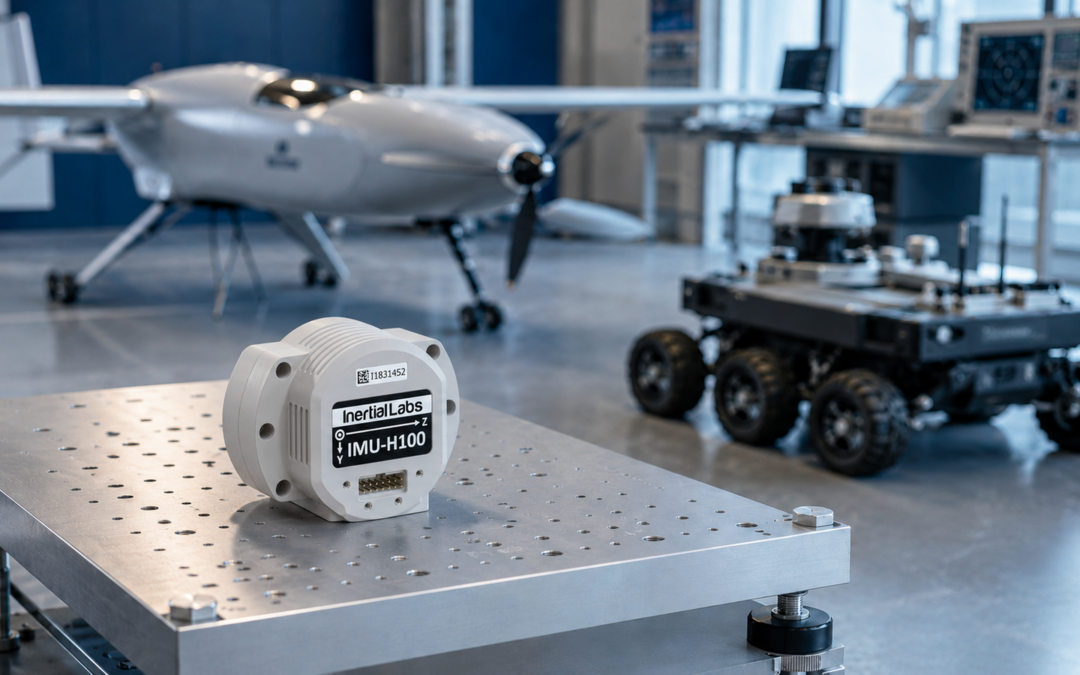
An inertial measurement unit, or IMU, is the motion-sensing core inside many modern navigation, guidance, stabilization and control systems. From unmanned aerial vehicles and autonomous ground platforms to aircraft, marine systems, gimbals and industrial machinery, an IMU continuously measures how a platform accelerates and rotates.
Unlike GNSS, an IMU does not need signals from satellites or external infrastructure to sense motion. This makes inertial measurement technology particularly valuable when GNSS signals are blocked, degraded, jammed or temporarily unavailable. However, an IMU should not be confused with a complete inertial navigation system: it supplies the measurements from which higher-level systems calculate attitude, velocity and position.
This guide explains what an IMU measures, how it works, how it differs from an AHRS and an INS, which specifications determine performance, and how to select the right sensor for demanding applications.
What Is an Inertial Measurement Unit?
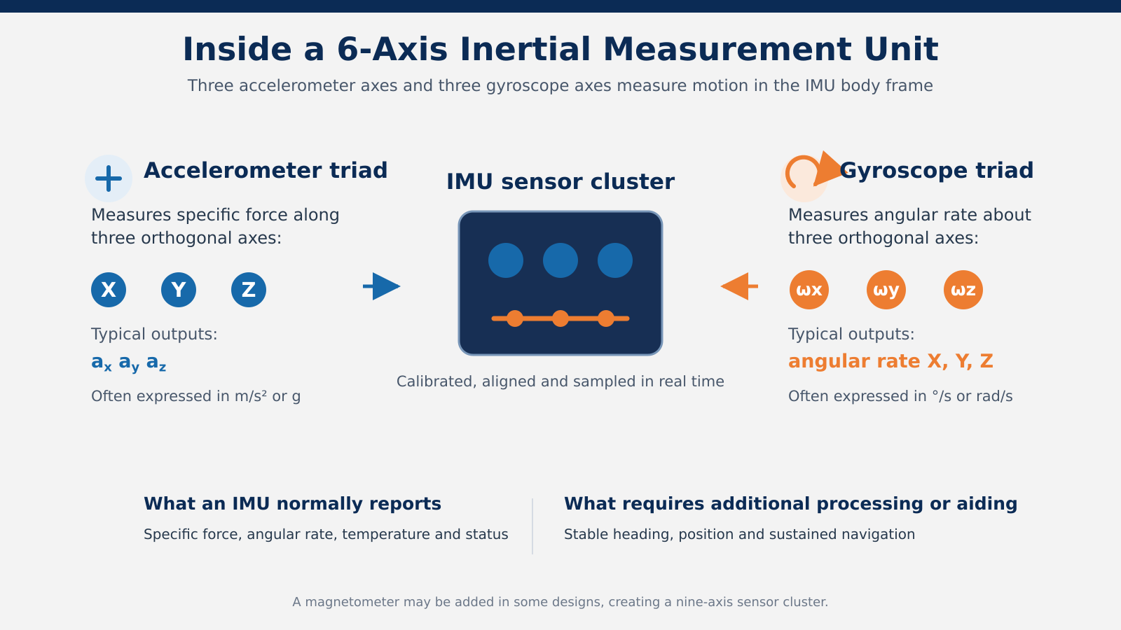
An inertial measurement unit is an electronic sensor assembly that normally combines three accelerometers with three gyroscopes mounted along mutually perpendicular X, Y and Z axes. This six-axis arrangement measures motion in three dimensions.
The accelerometers measure specific force along each axis, while the gyroscopes measure angular rate around each axis. Some devices also include a three-axis magnetometer, creating what is often marketed as a nine-axis sensor cluster. Whether the magnetometer is integrated, external or absent depends on the product and application.
A professional IMU may also include signal conditioning, temperature sensors, calibration data, timing and synchronization functions, built-in test capabilities, digital filtering and communication interfaces. These features convert individual sensor elements into a stable, aligned and integration-ready measurement unit.
What Does an IMU Measure?
Accelerometers: Specific Force and Linear Motion
Accelerometers respond to specific force along the body axes of the IMU. In practical system descriptions, this is often referred to as linear acceleration. The distinction matters because an accelerometer at rest on Earth still responds to the support force opposing gravity. Navigation algorithms must therefore account for gravity and platform orientation before acceleration can be integrated into velocity and position.
Gyroscopes: Angular Rate
Gyroscopes measure the rate of rotation about the X, Y and Z axes. Their measurements allow a processor to determine how quickly the platform is rolling, pitching or yawing. When angular-rate data is integrated over time and corrected for errors, it contributes to an estimate of attitude and orientation.
Magnetometers: Optional Heading Reference
A magnetometer measures the strength and direction of the local magnetic field. It can support heading estimation, but nearby ferrous materials, electrical currents and platform structures may distort the measurement. For this reason, professional systems often require magnetic calibration or use alternative heading references such as dual-antenna GNSS, gyrocompassing or other aiding sensors.
How Does an IMU Work?
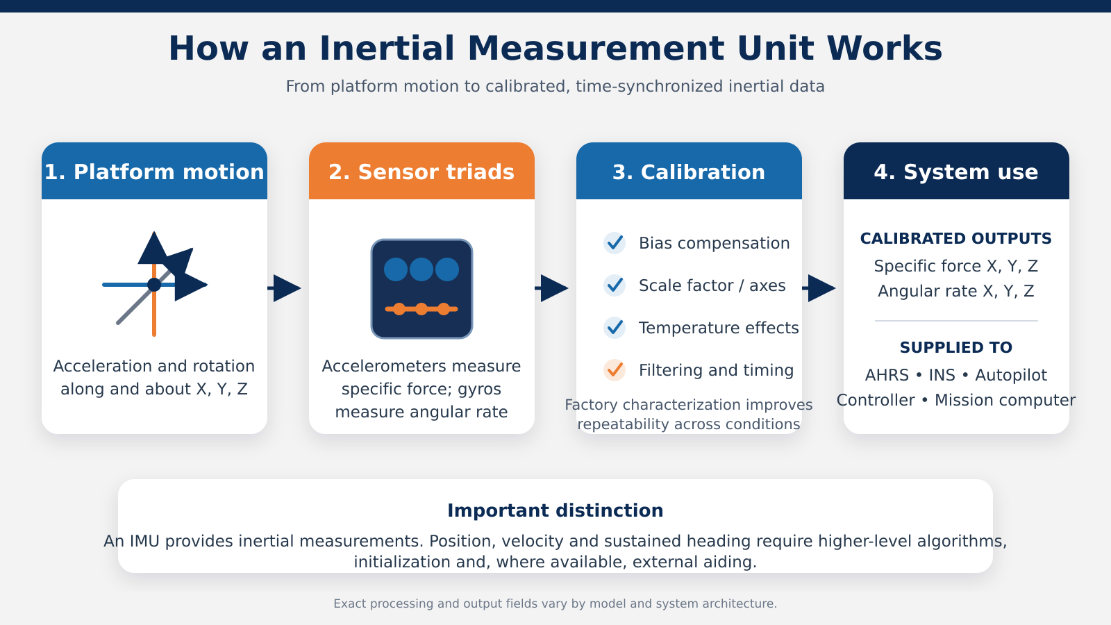
Most modern IMUs use a strapdown architecture. The sensors are rigidly attached to the platform, so all measurements are initially expressed in the IMU body frame. A processor samples the accelerometers and gyroscopes at a defined rate, applies calibration and compensation, and sends the resulting data to a flight computer, control system, AHRS or navigation computer.
The basic measurement process is:
- Sense specific force along the X, Y and Z axes.
- Sense angular rate about the X, Y and Z axes.
- Apply factory calibration, axis alignment and temperature compensation.
- Filter and time-stamp the measurements.
- Transmit inertial data to the host system for attitude, stabilization, guidance or navigation processing.
The IMU itself normally reports inertial measurements rather than absolute geographic position. A higher-level algorithm transforms those measurements between coordinate frames, removes gravity where appropriate, estimates orientation and integrates acceleration over time.
IMU Output and Reference Frames
IMU outputs are typically referenced to the sensor body frame. Correct installation orientation is therefore essential. If the physical sensor axes do not match the platform axes, the integration software must apply the correct transformation. Even a small uncorrected mounting or axis-alignment error can affect pointing, stabilization and navigation accuracy.
Common IMU output fields include:
- X, Y and Z specific-force or acceleration measurements
- X, Y and Z angular-rate measurements
- Sensor temperature
- Status and built-in test information
- Timing or synchronization data
- Filtered pitch and roll on selected integrated models
Output format, data rate, latency and synchronization options should be checked against the host computer and control-loop requirements before integration.
IMU vs AHRS vs INS: What Is the Difference?
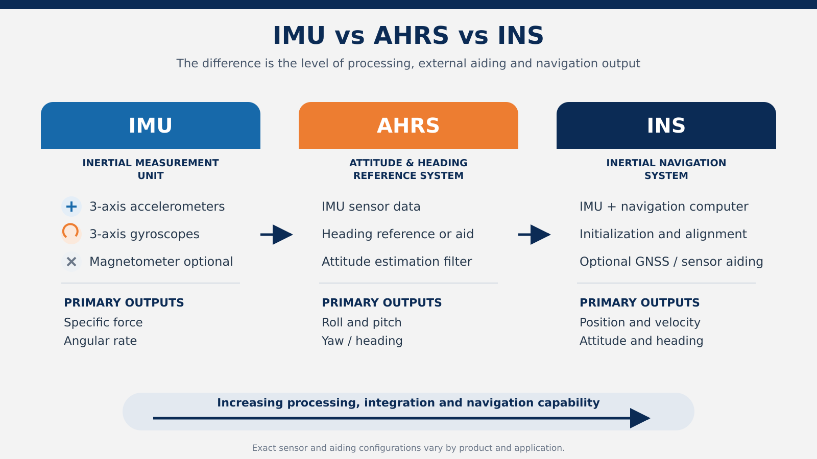
The terms IMU, AHRS and INS are related, but they describe different levels of functionality.
IMU – Inertial Measurement Unit:
Measures specific force and angular rate. It supplies the core motion data used by higher-level systems.
AHRS – Attitude and Heading Reference System:
Combines inertial measurements with filtering and a heading reference or aiding source to estimate roll, pitch and yaw or heading.
INS – Inertial Navigation System:
Combines an IMU with a navigation computer, initialization data and often GNSS or other aiding sensors to calculate position, velocity and attitude.
Product architectures vary, and some devices combine more than one function in a single enclosure. The most reliable way to compare products is to review their actual sensor inputs, algorithms and outputs rather than relying only on the product name.
Why IMU Accuracy Depends on Calibration
An IMU does not deliver high performance simply because it contains high-quality sensor elements. Its accelerometers and gyroscopes must be characterized, aligned and compensated as a complete assembly. Professional calibration typically addresses sensor bias, scale factor, non-linearity, cross-axis sensitivity, axis misalignment and temperature-dependent behavior.
Temperature is especially important. Bias and scale-factor errors can change as the device heats or cools, so an IMU intended for demanding outdoor, aerospace or defense applications should be calibrated across its specified operating temperature range. The mechanical installation also matters: vibration, shock, structural flex and poor mounting can introduce errors that are not visible in static bench testing.
Key IMU Performance Specifications
When comparing inertial measurement units, the following specifications are particularly important:
- Gyroscope bias in-run stability. Indicates how stable the gyro bias remains during operation under defined test conditions. Lower values generally support better inertial performance.
- Accelerometer bias stability. Describes the stability of accelerometer zero offset. Small bias errors can grow into velocity and position errors after integration.
- Angular Random Walk (ARW). Characterizes gyroscope noise that contributes to uncertainty in integrated angle.
- Velocity Random Walk (VRW). Characterizes accelerometer noise that contributes to uncertainty in integrated velocity.
- Bias repeatability. Describes how closely the sensor returns to the same bias after power cycles or environmental changes.
- Scale-factor accuracy and non-linearity. Describe how accurately output follows the applied acceleration or rotation across the measurement range.
- Dynamic range. Defines the maximum angular rate and acceleration the IMU can measure without saturation.
- Bandwidth and output data rate. Determine whether the sensor can capture the platform dynamics and support the required control-loop frequency.
- Axis alignment. Quantifies how accurately the sensing axes match the defined orthogonal coordinate system.
- Latency and timing. Are critical when IMU measurements must be synchronized with GNSS, cameras, LiDAR, radar, control surfaces or mission computers.
MEMS and FOG-Based IMUs
MEMS IMUs use microelectromechanical gyroscopes and accelerometers. They can be compact, lightweight, power-efficient and cost-effective, with performance ranging from basic industrial sensing to tactical and high-performance navigation applications. Their small size makes them particularly attractive for UAVs, robotics, gimbals, autonomous platforms and embedded systems.
FOG-based IMUs use fiber optic gyroscopes together with precision accelerometers. They generally offer lower gyro noise and stronger long-term stability than many MEMS solutions, but they are usually larger, heavier and more expensive. FOG technology is appropriate when the mission requires demanding navigation, gyrocompassing, pointing or stabilization performance that justifies the additional size, weight, power and cost.
IMU Performance Grades
IMUs are commonly described as consumer, industrial, tactical or navigation grade. These labels provide a useful general indication of performance, but the boundaries are not universal across manufacturers. Gyroscope bias stability is one important benchmark, yet the complete error budget, environmental calibration, repeatability, noise, dynamic range and application requirements must also be considered.
- Consumer-grade sensors prioritize very low cost and size for everyday electronics.
- Industrial-grade IMUs support machinery, robotics, vehicles and stabilization where reliable calibrated motion data is required
- Tactical-grade IMUs provide lower drift, better repeatability and stronger environmental performance for demanding guidance, control and short-term inertial navigation.
- Navigation-grade sensors target the lowest drift and highest long-term accuracy for missions that must sustain inertial performance for longer periods.
How IMUs Support GPS-Denied Navigation
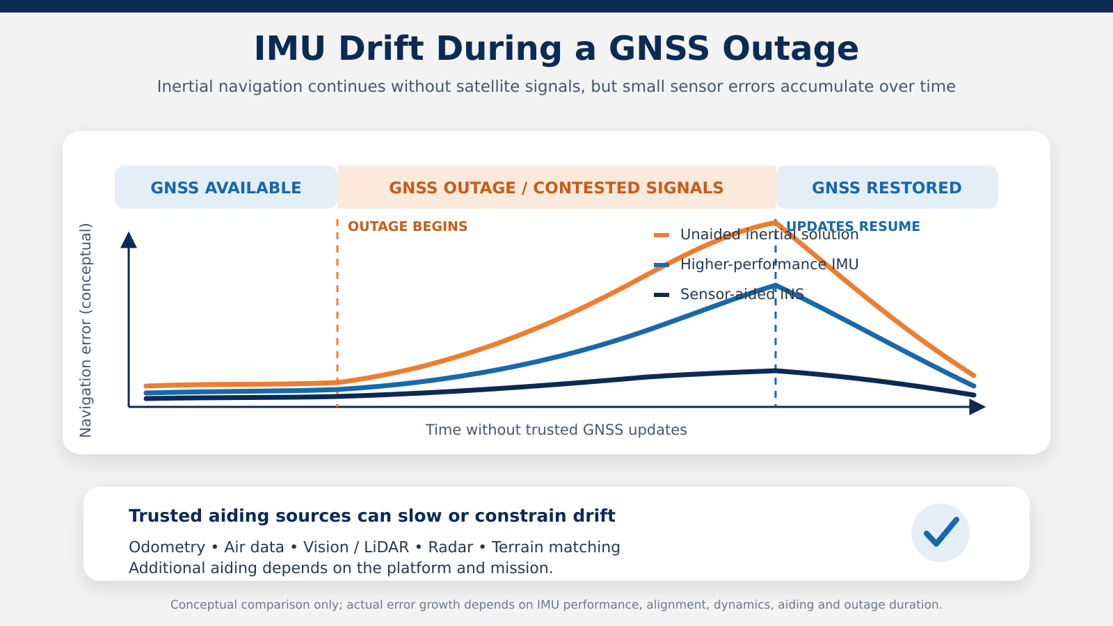
An IMU continues measuring acceleration and angular rate when GPS or other GNSS signals are unavailable because it does not depend on external radio signals. Inside an INS, those measurements support dead reckoning and help maintain attitude, velocity and position estimates during a GNSS outage.
However, inertial errors accumulate over time. Small gyro and accelerometer errors are integrated by the navigation equations, causing attitude, velocity and position drift. A higher-performance IMU slows this error growth, but it does not eliminate it. Extended GPS-denied operation normally requires careful system design and may use aiding from odometers, air-data sensors, magnetometers, cameras, LiDAR, radar, terrain matching or other trusted references.
For this reason, an IMU is best understood as a foundational element of resilient navigation and Assured Positioning, Navigation and Timing (APNT), not as a complete replacement for every external positioning source.
Common IMU Applications
Inertial measurement units support any platform that needs continuous motion, attitude or control data. Common applications include:
- UAV flight control, guidance and navigation
- UGV and autonomous vehicle localization
- AUV, ROV and maritime platform motion sensing
- EO/IR gimbal and line-of-sight stabilization
- Antenna pointing and tracking
- Aircraft attitude and control systems
- Precision-guided and high-dynamics platforms
- Robotics and industrial motion control
- Railway acceleration, deceleration and ride-quality monitoring
- LiDAR, photogrammetry and mobile-mapping systems

How to Choose the Right IMU
The best IMU is not automatically the model with the lowest published bias value. Selection should begin with the platform dynamics, required outputs and complete system architecture.
- Define whether the IMU will support stabilization, attitude estimation, guidance, navigation or measurement.
- Estimate the required inertial accuracy and the maximum expected GNSS outage duration.
- Match angular-rate and acceleration ranges to the real platform dynamics, including shock events.
- Check data rate, bandwidth, latency and synchronization requirements.
- Confirm operating temperature, vibration, shock, environmental protection and EMI/EMC requirements.
- Review size, weight, power, connector and communication-interface constraints.
- Verify factory calibration, temperature compensation, documentation and integration support.
- Evaluate the complete system error budget instead of selecting from one headline specification.
Frequently Asked Questions About IMUs
Can an IMU provide position by itself?
A basic IMU normally provides acceleration and angular-rate measurements, not absolute position. Position is estimated when an inertial navigation algorithm combines IMU data with initial conditions and, where available, external aiding.
Does an IMU work without GPS?
Yes. The IMU continues sensing motion without GPS. In a navigation system, this supports continuity during GPS loss, but position error grows over time. Higher-performance inertial sensors can slow error growth, while trusted external aiding sources can constrain drift.
What is the difference between a six-axis and nine-axis IMU?
A six-axis IMU combines three accelerometer axes and three gyroscope axes. A nine-axis sensor cluster adds a three-axis magnetometer. The added magnetic measurements can support heading estimation, but they are sensitive to local magnetic disturbances.
Is a tactical-grade IMU always better?
A tactical-grade IMU generally offers lower drift and better repeatability than an industrial-grade device, but it may also increase cost, size or integration complexity. The correct choice depends on the required performance and mission duration.
Conclusion
An inertial measurement unit is the sensing foundation of modern attitude, stabilization, guidance and inertial navigation systems. By measuring specific force and angular rate along three axes, it provides continuous motion data without relying on external signals. Its real-world value depends on sensor quality, calibration, temperature compensation, installation, timing and the algorithms that use its measurements.
General Guidance provides compact industrial-grade and tactical-grade MEMS IMUs, navigation-focused models and FOG-based inertial measurement units from Inertial Labs, a VIAVI Solutions company. Our team helps customers compare performance, environmental and integration requirements and identify the appropriate IMU for UAVs, UGVs, aerospace, defense, maritime, mapping, stabilization and motion-control applications.
Explore our Inertial Measurement Units or contact General Guidance to discuss your platform, accuracy and integration requirements.